So I understand correctly that when I ride the Acela next month the train could operate at 160 mph?
You are using an out of date browser. It may not display this or other websites correctly.
You should upgrade or use an alternative browser.
You should upgrade or use an alternative browser.
NEC state of good repair work and planned service expansion
- Thread starter Acela150
- Start date

Help Support Amtrak Unlimited Discussion Forum:
This site may earn a commission from merchant affiliate
links, including eBay, Amazon, and others.
jis
Permanent Way Inspector
Staff member
Administator
Moderator
AU Supporting Member
Gathering Team Member
In RI and MA, yes. Of course depends on how soon your next ride is. The current Acela sets will not run at 160 AFAIK. The Acela IIs will.So I understand correctly that when I ride the Acela next month the train could operate at 160 mph?
You can find everything of importance in the mathematics of catenary on the following page:The mathematics of CAT can become complicated.
https://math24.net/equation-catenary.html
The bottom line catenary equation is:
y = a cosh(x/a)
In most places they have installed the constant tension catenary on completely new set of poles and left the old poles in place where they carry high tension lines and removing those that don't. In a few places even the high tension lines have been moved to the new poles. I guess that is determined by how deteriorated the old poles in question are.How does Amtrak replaces poles at say 120 feet or just a new pole between present poles spacing them 90 feet apart. That is a decision of engineering. PRR poles carry the 12.0 kV, the 169 kV single phase Amtrak transmission lines, and at some locations 3 phase electrical utility transmission 250+ kV wires. The PRR poles are steel buried directly into the ground with many rusting away below ground level. From time to time new poles are installed on concrete foundations at those locations in the ground keeping steel poles above ground water. Have no idea what spacings may happen at each location.
The new poles all appear to have cross beams. AFAICT none have the cross suspension wires.
Last edited:
- Joined
- Feb 18, 2003
- Messages
- 8,526
In RI and MA, yes. Of course depends on how soon your next ride is. The current Acela sets will not run at 160 AFAIK. The Acela IIs will.
You can find everything of importance in the mathematics of catenary on the following page:
https://math24.net/equation-catenary.html
The bottom line catenary equation is:
y = a cosh(x/a)
With high speed rail, the optimum catenary span length is largely a factor of the design train speed. The action of the pantograph sliding along the contact wire imparts some significant dynamics such as waves and oscillations into the catenary system. The longer the span between supporting structures and the higher the design speed, the greater the magnitude of those wire movements. If large enough, those wire movements can cause loss of pantograph electrical contact and mechanical damage to the system. Thus, for any given design speed there is an ideal span length - spans long enough to minimize supporting structure cost and short enough to prevent operational issues and damage from dynamics.
Technically speaking, electrified railroad "catenary" is not catenary in the geometric sense. The sagged strength component wire (called the catenary wire) supports the contact system (messenger and trolley wires) with vertical hangers spaced every so often. It's more like a suspension bridge with the weight transferred to the supporting cable at points, not uniformly. Today's analytic capability permits exact calculations of catenary system loads and wire forces based on the real geometry of the entire system. In the olden days, shortcuts like assuming a parabolic shape made calculation using pencil, paper and slide rules possible.
Here’s looking south from NRK.That makes sense.
When they do constant tension they install new posts because one of the things that goes with constant tension is also reducing the span length to something shorter than what PRR used originally. That is to reduce sideways deflection of catenary I suppose, and get a more stable catenary.

Most of the work is north of NRK but I didn’t get a good shot of it.

jis
Permanent Way Inspector
Staff member
Administator
Moderator
AU Supporting Member
Gathering Team Member
Technically speaking, electrified railroad "catenary" is not catenary in the geometric sense. The sagged strength component wire (called the catenary wire) supports the contact system (messenger and trolley wires) with vertical hangers spaced every so often. It's more like a suspension bridge with the weight transferred to the supporting cable at points, not uniformly. Today's analytic capability permits exact calculations of catenary system loads and wire forces based on the real geometry of the entire system. In the olden days, shortcuts like assuming a parabolic shape made calculation using pencil, paper and slide rules possible.
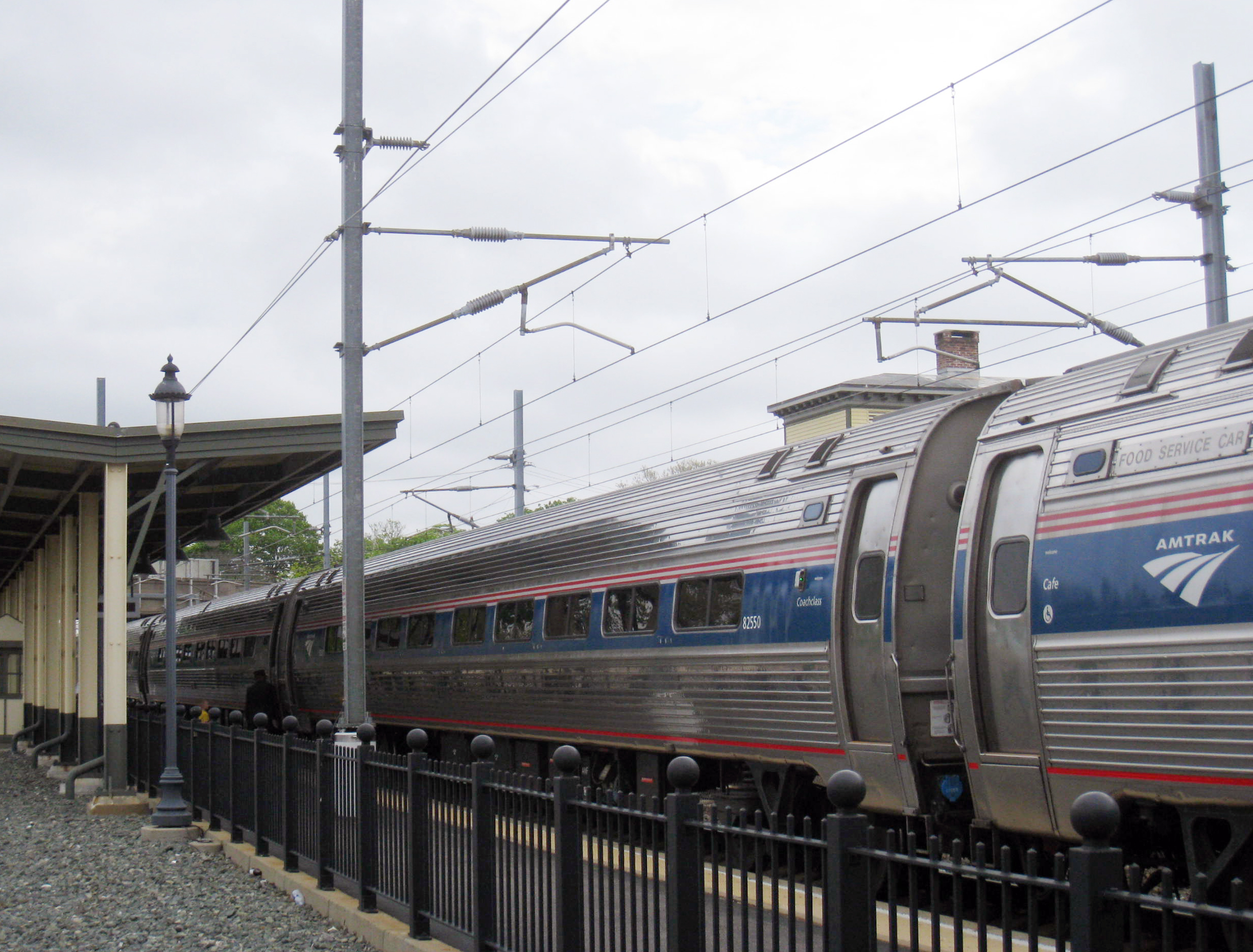
Interestingly, NEC South with its 11-12.5kV electrification appears to use three wires referred to as (from top to bottom) Catenary, Messenger and Trolley or Contact, as they came with the original PRR electrification. The new constant tension uses three wires in this territory too. The new 25kV electrification up north does not have the middle wire. See photo below. Nor does the new MNRR, even though they are 12.5kV.

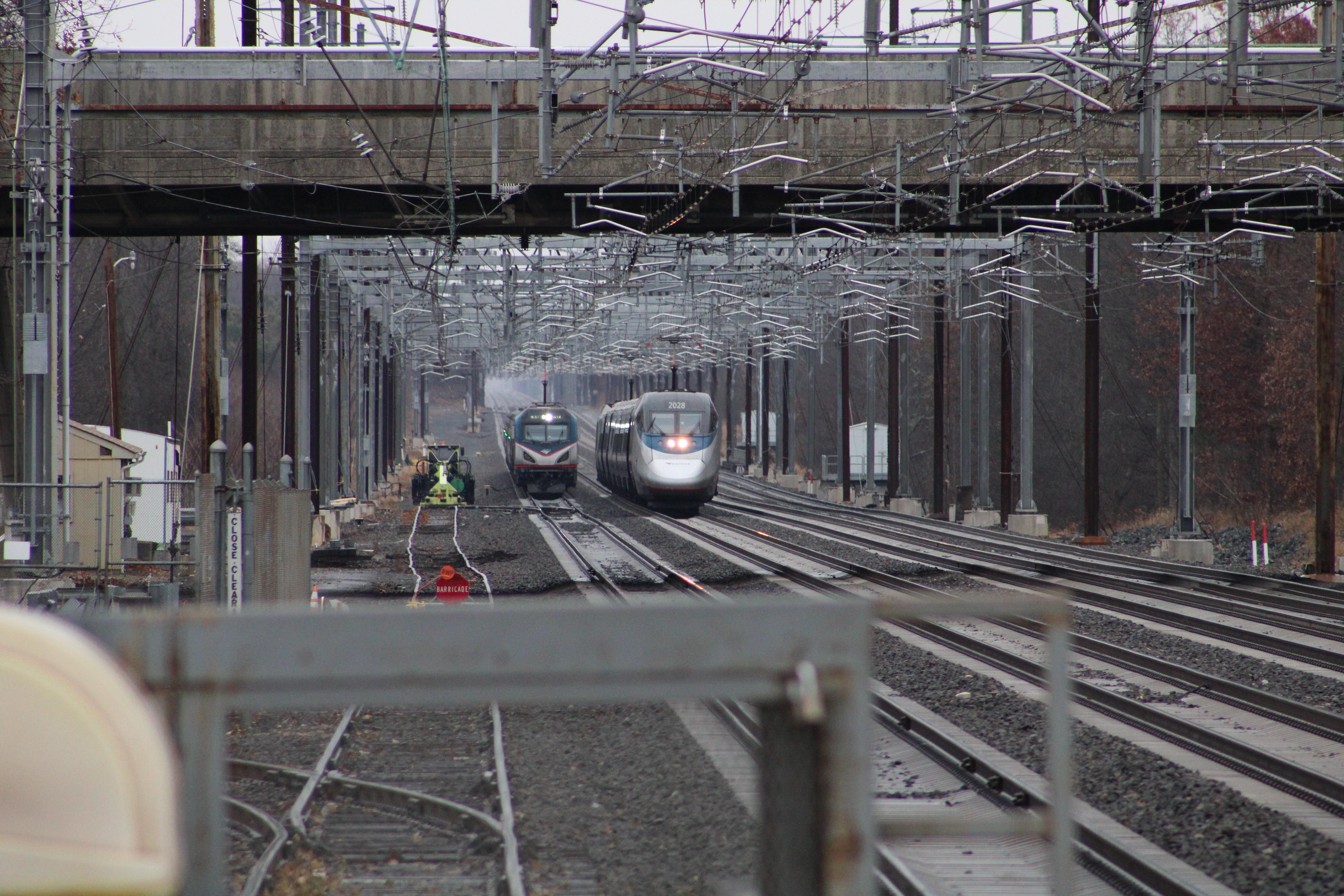
The additional middle wire makes the catenary installation considerably more complex as is apparent in this photo of the new three wire constant tension catenary at Princeton Jct.

I wonder what determines whether to use the third wire or not.
In other countries, in 25kV electrifications more often than not there is no middle wire and sometimes the top wire is referred to as Messenger Wire. See for example:
http://www.railway-technical.com/infrastructure/electric-traction-power.html
As usual all as clear as mud!
Incidentally, the following article from 2019 gives the impression that even County to Midway constant tension catenary is back on the table. So far I have heard nothing definitive from any reliable source about it.
https://www.railwaypro.com/wp/amtrak-and-nj-transit-to-improve-nec-infrastructure/
Last edited:
- Joined
- Aug 3, 2020
- Messages
- 7
No speed increase as of yet. Guess I'll just keep an eye on the tracker to see if Amtrak ever gets around to implementing the change.

$4.00
Completion of the First Transcontinental Railroad trading card (Promontory Summit Utah, 5/10/1869) 2009 Topps Heritage #113
Autograph Warehouse (AW Authentic)

$21.75
Scenes Along The Oversea Railroad - Key West Extension Florida - 1919 Curt Teich Souvenir Postcard Folder #1039
grinvideoproductions

$20.99
$27.98
Walthers Trainline HO Scale Model Flatcar with Logging Crane - Alaska Railroad 17104, Blue
Amazon.com
Acela150
Super Buff
No speed increase as of yet. Guess I'll just keep an eye on the tracker to see if Amtrak ever gets around to implementing the change.
ACSES related.
nti1094
Service Attendant
- Joined
- Apr 9, 2015
- Messages
- 152
Nothing south of New York has grade crossings anymore. There are a couple in New England.Do those sections have no grade crossings?
ACSES related.
Any updated timeline for implementing the higher speeds?
cirdan
Engineer
- Joined
- Mar 30, 2011
- Messages
- 3,849
That makes sense.
When they do constant tension they install new posts because one of the things that goes with constant tension is also reducing the span length to something shorter than what PRR used originally. That is to reduce sideways deflection of catenary I suppose, and get a more stable catenary.
Maybe it is also that the PRR installations must be simply ancient by now and at some point you just need to bite the bullet and replace old by new. That is probably a better strategy long term than. trying to graft new catenary onto old supports whose condition and remaining lifespan may be questionable.
- Joined
- Aug 3, 2020
- Messages
- 7
I was on 19 Crescent nyp-cvs about a month ago. When the train would get up to speed on the NEC (presumably 110 mph) the Amtrak Jiggle was pretty outrageous, reading was problematic and writing unlikely.
I was on 19 Crescent nyp-cvs about a month ago. When the train would get up to speed on the NEC (presumably 110 mph) the Amtrak Jiggle was pretty outrageous, reading was problematic and writing unlikely.
I find the Shore Line east of New Haven and up to Boston to be the smoothest part of the NEC by far. The times I've been on the Keystone, it was also smooth.
https://thepointsguy.com/news/acela-trains-faster-on-northeast-corridor/If you’re feeling the need for more speed on Amtrak’s popular Northeast Corridor route, there’s some good news coming down the tracks. Recent infrastructure improvements in New Jersey will allow Acela trains to whiz through a section of the Garden State at speeds up to 150 mph.
According to Amtrak, these speeds are the fastest in North America and match the top speeds currently achieved in parts of Massachusetts and Rhode Island. Additionally, when the full infrastructure upgrades are introduced in the fall of 2023, Amtrak’s spiffy new Acela trains will be able to achieve speeds of 160 mph — allowing ever-shorter trip times on the perpetually popular Northeast Corridor in the years ahead.
Forget 150 mph, if they really want to shorten trip times to Boston, Metro-North needs to do something with the line between New Rochelle and New Haven so the trains can consistently travel 70 mph.
jis
Permanent Way Inspector
Staff member
Administator
Moderator
AU Supporting Member
Gathering Team Member
From Railway Age on the speed limit increase in NJ...
https://www.railwayage.com/passenger/high-performance/amtrak-increasing-acela-speeds-in-new-jersey/
https://www.railwayage.com/passenger/high-performance/amtrak-increasing-acela-speeds-in-new-jersey/
Is similar work being done elsewhere in the NEC to allow for such speeds? I know Acela can reach 135 MPH between the Susquehanna River and Wilmington. Any work to allow 150 (eventually 160 with the new trainsets) there as well?
George Harris
Engineer
A certain amount of lateral deflection is desirable. Otherwise with good track where there is very little side to side rocking of the equipment, the contact wire will wear a groove into the pantograph cross bar. Generally there is a design amount of zig zag in the wire alignment.When they do constant tension they install new posts because one of the things that goes with constant tension is also reducing the span length to something shorter than what PRR used originally. That is to reduce sideways deflection of catenary I suppose, and get a more stable catenary.
jis
Permanent Way Inspector
Staff member
Administator
Moderator
AU Supporting Member
Gathering Team Member
Yup, the zig-zag is an integral part of the new catenary in NJ, including the parts that are not constant tension but use new more sturdy and rigid suspension.A certain amount of lateral deflection is desirable. Otherwise with good track where there is very little side to side rocking of the equipment, the contact wire will wear a groove into the pantograph cross bar. Generally there is a design amount of zig zag in the wire alignment.
They have to change out the catenary and put in constant tension or minimally the more rigid suspenders. Apparently with the latter they can push it to 140 or 145, but for anything above that it has to be constant tension.Is similar work being done elsewhere in the NEC to allow for such speeds? I know Acela can reach 135 MPH between the Susquehanna River and Wilmington. Any work to allow 150 (eventually 160 with the new trainsets) there as well?
With the Infrastructure Bill they potentially have the money to do the Delaware-Maryland segment (Ragan to Perry IIRC), but have not seen any developments on it yet. OTOH, they are working on completing the constant tension all the way to Trenton and rumor has it that they will complete the Midway to County too eventually.
Last edited:
There are recently released NEC commission program documents that appear to show, in my opinion, that the New Jersey High Speed Rail Improvement Program has been extended from New Brunswick-Newark, NJ which represent a clear expansion of the previous version of this program that resulted in the recent speed increase between Ham-County (currently CP Clark-County only). So, for now, they are sticking to NJ and I have not found any mention of any tensioning work in DE, MD, or PA.Yup, the zig-zag is an integral part of the new catenary in NJ, including the parts that are not constant tension but use new more sturdy and rigid suspension.
They have to change out the catenary and put in constant tension or minimally the more rigid suspenders. Apparently with the latter they can push it to 140 or 145, but for anything above that it has to be constant tension.
With the Infrastructure Bill they potentially have the money to do the Delaware-Maryland segment (Ragan to Perry IIRC), but have not seen any developments on it yet. OTOH, they are working on completing the constant tension all the way to Trenton and rumor has it that they will complete the Midway to County too eventually.
The old version of NJHSRIP always only referenced Trenton-New Brunswick. So, any mention of some sort of cat work north of New Brunswick is significant. They appear intent on finishing Clark-Ham to allow further speed upgrades from south of Princeton Junction to through Hamilton station just short of Trenton, before taking the work north past South Brunswick (Midway Interlocking) which is where the current tensioning ends. It doesn't sound like they've decided on the exact parameters yet.
Hoping this results in higher speeds throughout more of New Jersey, eventually.
https://nec-commission.com/app/uplo...nvestment-Plan-02-Appendix-Amended-Mar-22.pdf
Page A2-82 for some updates and project scope, Clark to Ham Constant Tension Upgrade Project
Page A3-160 for NJHSRIP
cirdan
Engineer
- Joined
- Mar 30, 2011
- Messages
- 3,849
CAT wire is not installed straight but side to side. That enables the contact portion of the pan to not wear out to replacement. Otherwise the CAT would wear a groove on the PAN contact surface.
The mathematics of CAT can become complicated. Any constant weight wire hangs by the attach points in a curve called catenary, I cannot find the formula. AS I understand it PRR variable tension poles are nominally 180 feet apart on straight track. The standard for constant tension is 120 feet. Believe the sag is 1/2 at 120 feet with no tension. Placing weights approximately 4000 # reduces the sag greatly between attach points. The weights keep a constant tension on wires expanding when hot . Weight distances are ~ 1300 feet apart with a no movement fixed hanger at mid point.
Weights may be closer depending on amount of temperature variation. That is why CAT wires have hangers that move laterally with the expansion and contraction of the CAT wires. I understand that they have a balance point temp where hangers are all supporting CAT straight down.
How does Amtrak replaces poles at say 120 feet or just a new pole between present poles spacing them 90 feet apart. That is a decision of engineering. PRR poles carry the 12.0 kV, the 169 kV single phase Amtrak transmission lines, and at some locations 3 phase electrical utility transmission 250+ kV wires. The PRR poles are steel buried directly into the ground with many rusting away below ground level. From time to time new poles are installed on concrete foundations at those locations in the ground keeping steel poles above ground water. Have no idea what spacings may happen at each location.
The calculation of the shape of a free hanging cable is a standard base-level topic when you study physics or engineering, and is likely to come up in tests and quizzes, which is why most students learn it by heart but then forget it later. Its obviously not something most of us need very often.
Basically the shape by which a cable hangs follows the cosh function (also called the hyperbolic cosine).
If you want to know the details, wikipedia is your friend (Hyperbolic functions - Wikipedia). The math looks daunting at first but a lot of it is quite intuitive and common sense when you get into it.
This shape is by mathematicians sometimes also called "the catenary curve".
Last edited:
jis
Permanent Way Inspector
Staff member
Administator
Moderator
AU Supporting Member
Gathering Team Member
Here is a very nice article from Railway Age dating back to 2015 discussion of various design and engineering considerations for the New Jersey High Speed Rail Improvement Project (NJHSRIP) :
https://www.railwayage.com/cs/hsr-in-the-northeast-what-next/?RAchannel=home
https://www.railwayage.com/cs/hsr-in-the-northeast-what-next/?RAchannel=home
This is a very informative article on this whole thing. It would really be great if they could write a follow on piece now that speed increases have actually taken effect and further work is clearly being discussed. Amtrak as an agency is flushed with cash too from multiple *****-related stimulus bills and now the especially the infrastructure bill.Here is a very nice article from Railway Age dating back to 2015 discussion of various design and engineering considerations for the New Jersey High Speed Rail Improvement Project (NJHSRIP) :
https://www.railwayage.com/cs/hsr-in-the-northeast-what-next/?RAchannel=home
In that article, they even floated the idea of modifying the reverse curve past Midway Interlocking to potentially allow for even higher speeds than 160MPH (!) This probably is a much lower priority than countless other Special Projects so no one hold your breath! It's good to know they have discussed it though.
"A speed-restricted reverse curve limited to 130 to 140 mph depending on equipment considerations exists between MP 39 and MP 40. The original concept called for realigning these curves to achieve 160 mph"...
Follow up would be great on this. How fast can the AX-2 sets take a big curve like this? This article is using the old AX-1 sets to discuss speed limitations. My understanding is the AX-1 sets apparently do not track very well on curves and the "130 - 140" SR is therefore equipment related not necessarily curve related.
jis
Permanent Way Inspector
Staff member
Administator
Moderator
AU Supporting Member
Gathering Team Member
This fall there is a big study coming up evaluating cant deficiency for AX-2 sets. I guess some of the answers will come out of that study.
Recent trip from NYP to BOS on Acela, I had forgotten how SLOW this and other trains actually go between New Haven and New Rochelle, YET we still came in to New Haven TEN MINUTES under the advertised on the schedule - during rush hour. I’m not sure if we ever hit 70 mph - it was stop and go the whole time. We were even TEN MINUTES early into Boston. Been a long haul of upgrades on this section, and over a pretty long time. Not sure how close progress is towards some sort of improvement. But long over due and now with recent speed increases and work done on other portions of NEC, this section really stands out - to me at least. Good show though overall, with Acela and onboard staff….
Latest posts
-
-
New North Brunswick NJT station on the NEC
- Latest: Touchdowntom9
-
-
-
-
-
-


