I have a question about electrical systems. I'm in Japan at the moment and have been taking a lot of trains, both high-speed and "local" (which is what non-high-speed trains are often called here, whether inter- or intra- city), and I notice that while the Shinkansen high-speed runs at 25kv AC, almost all locals run at 600-1500 v DC, and some of these locals are hitting around 80 mph. Both are mostly overhead catenary, including subway trains. I know that AC is more efficient for long-distance use, but given the difference in voltages, is it the case that motive power is mostly determined by current rather than voltage ?
You are using an out of date browser. It may not display this or other websites correctly.
You should upgrade or use an alternative browser.
You should upgrade or use an alternative browser.
Voltage/Current
- Thread starter Aristotle
- Start date


Help Support Amtrak Unlimited Discussion Forum:
This site may earn a commission from merchant affiliate
links, including eBay, Amazon, and others.
The power output of a locomotive (or train in the case of an EMU) is a combination of current and voltage. The lower the voltage, the more current is needed to achieve a given number of Watts.
The main reason that AC is more efficient for longer distances is that it can be transmitted at a high voltage then transformed down to the voltage needed to run the train. For example the power supply for Amtrak's NEC is transmitted at 138 KV then transformed down to 12 KV at substations. For DC you can distribute it to the substations as AC but then have to transform and rectify it from AC to DC which is a more complex process, then feed the catenary with fairly heavy feeders since the voltage is lower.
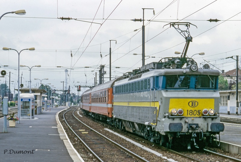
Most DC systems are legacy because in the early days of electrification the technology wasn't there yet for motor control of 50/60 HZ AC. For local and suburban trains it still works pretty well. A number of European countries still use DC for example Italy and Belgium use 3 KV DC except for certain high speed lines.,
The main reason that AC is more efficient for longer distances is that it can be transmitted at a high voltage then transformed down to the voltage needed to run the train. For example the power supply for Amtrak's NEC is transmitted at 138 KV then transformed down to 12 KV at substations. For DC you can distribute it to the substations as AC but then have to transform and rectify it from AC to DC which is a more complex process, then feed the catenary with fairly heavy feeders since the voltage is lower.
Most DC systems are legacy because in the early days of electrification the technology wasn't there yet for motor control of 50/60 HZ AC. For local and suburban trains it still works pretty well. A number of European countries still use DC for example Italy and Belgium use 3 KV DC except for certain high speed lines.,
Thanks. That clarifies some things for me. I think I didn't take into account, also, the difference between what is sent through the catenary system and what voltage/current actually hits the electric motors. After that 138KV gets stepped down at a substation on the NEC, does it hit the motors at 12kv or is it stepped down again ? Also, since DC motors are typically using lower voltages are they therefore larger and heavier than AC motors ?
cirdan
Engineer
- Joined
- Mar 30, 2011
- Messages
- 3,940
Traction motors typically work at voltage between 500V and 800V, exceptionally up to 1500 or 2000V. Higher voltages would require more insulation, which engenders geometrical problems (railroad traction motors are typically more compact than say industrial motors of similar ratings). If you have 25kV on the catenary, this needs to be stepped down and converted.
Way back when, in the days of the GG-1 and older motors, they transformed the AC down to 600 V or so but still ran the traction motors off of AC. This is one reason why they used 25 HZ as it worked better with the motors of the day.
Post WW2 with the rise of Diesel Electric and use of 600 VDC traction motors, the trend was to rectify the AC to DC and apply that to DC motors. This is how the PRR E44 freight locomotives and Silverliner fleets were powered. Originally using Ignitron rectifiers later converted to solid state.
Nowadays we have moved back to AC motors because modern AC motors can be built without commutators and brushes and such high maintenance items. To do this the DC is then inverted back to AC. This way the motor can be controlled by varying the voltage and frequency. If they ran them directly off the AC they would be stuck at one speed like a synchronous motor. As a matter of fact the Pennsy in 1917 built a locomotive the FF1 with AC synchronous motors which could only run at 2 speeds 10.3 and 20.6 mph and therefore was limited to use as a pusher on grades.
cirdan
Engineer
- Joined
- Mar 30, 2011
- Messages
- 3,940
Early electrification in Italy and also on some mountain lines in Switzerland used three phase AC, so typically you had two overhead lines, each with one phase, and the third phase using the ground return. The AC was typically at low frequency and was applied directly to the motors. In some cases motor speed could even be doubled/halved by switching the poles (so if you had say a 6 pole motor, you would apply the three phases P1,P2,P3,P1,P2,P3 at low speed and switch to P1,P1,P2,P2,P3,P3 for high speed). You could do star-delta switches to control the power, and had starting resistors. The fixed speed feature was quite useful for example on long uphill climbs on rack railways where you typically hold a constant speed regardless of everything else. These early examples used large diameter squirrel cage motors running at low rpm (sometimes the entire locomotive body was just the motor). Squirrel cage motors allow some phase slippage (and actually torque increases with phase slippage) so you could use that to accelerate.
Last edited:


$10.37
IA, Iowa Old Vintage Antique Collectables For Sale Newton and Northwestern Railroad Bridge Unused
Vintage Postcards - Towns in 50 USA States


$10.37
IA, Iowa Old Vintage Antique Collectables For Sale Illinois Central Railroad Bridge Missouri River 1940
Vintage Postcards - Towns in 50 USA States


$10.37
IA, Iowa Old Vintage Antique Collectables For Sale Illinois Central Railroad Bridge Missouri River Unused
Vintage Postcards - Towns in 50 USA States


$16.99
$22.99
Fodor's Best Road Trips in the USA: 50 Epic Trips Across All 50 States (Full-color Travel Guide)
Amazon.com


$4.00
Completion of the First Transcontinental Railroad trading card (Promontory Summit Utah, 5/10/1869) 2009 Topps Heritage #113
Autograph Warehouse (AW Authentic)


$20.99
$27.98
Walthers Trainline HO Scale Model Flatcar with Logging Crane - Alaska Railroad 17104, Blue
Amazon.com


$235.99
Pennsylvania Railroad William Atterbury Signed Auto Mounted Cut Index Card D13 - College Cut Signatures
Sports Memorabilia


Interesting. The PRR FF1 I mentioned above also used 3 phase motors, but was just a single phase feed from the 11KV 25 HZ catenary. They converted to 3 phase using motor generator sets onboard the locomotive.Early electrification in Italy and also on some mountain lines in Switzerland used three phase AC, so typically you had two overhead lines, each with one phase, and the third phase using the ground return. The AC was typically at low frequency and was applied directly to the motors. In some cases motor speed could even be doubled/halved by switching the poles (so if you had say a 6 pole motor, you would apply the three phases P1,P2,P3,P1,P2,P3 at low speed and switch to P1,P1,P2,P2,P3,P3 for high speed). You could do star-delta switches to control the power, and had starting resistors. The fixed speed feature was quite useful for example on long uphill climbs on rack railways where you typically hold a constant speed regardless of everything else. These early examples used large diameter squirrel cage motors running at low rpm (sometimes the entire locomotive body was just the motor). Squirrel cage motors allow some phase slippage (and actually torque increases with phase slippage) so you could use that to accelerate.
Forgive my ignorance here. So, in some cases the AC from the catenary is rectified to DC, then inverted back to AC for the motors ? What exactly is the purpose of that intermediate step ? why go through DC before going back to AC ?Way back when, in the days of the GG-1 and older motors, they transformed the AC down to 600 V or so but still ran the traction motors off of AC. This is one reason why they used 25 HZ as it worked better with the motors of the day.
Post WW2 with the rise of Diesel Electric and use of 600 VDC traction motors, the trend was to rectify the AC to DC and apply that to DC motors. This is how the PRR E44 freight locomotives and Silverliner fleets were powered. Originally using Ignitron rectifiers later converted to solid state.
Nowadays we have moved back to AC motors because modern AC motors can be built without commutators and brushes and such high maintenance items. To do this the DC is then inverted back to AC. This way the motor can be controlled by varying the voltage and frequency. If they ran them directly off the AC they would be stuck at one speed like a synchronous motor. As a matter of fact the Pennsy in 1917 built a locomotive the FF1 with AC synchronous motors which could only run at 2 speeds 10.3 and 20.6 mph and therefore was limited to use as a pusher on grades.
Control. Keep in mind that your inverters are providing power to the traction system typically through some type of VFD/IGBT arrangement but also (in passenger rail) typically sending 3 phase 480 down the train for HEP which in turn will be dropped where necessary for utilization.
Besides what PVD said above, it is also a different type of AC in terms of voltage and frequency etc. and I suspect it is harder to convert one type of AC directly to another, easier to go through the step of converting to DC then inverting back to AC.Forgive my ignorance here. So, in some cases the AC from the catenary is rectified to DC, then inverted back to AC for the motors ? What exactly is the purpose of that intermediate step ? why go through DC before going back to AC ?
The ability to invert, rectify, and control have been advanced considerably by the march forward of technology. Modern solid state equipment has made things that were theoretically doable into the practical and commonplace. In very long distance transmission HVDC is now common, (transform the generated AC to a very high voltage, rectify to DC for transmission on 2 instead of 3 conductors, invert back to AC at the destination grid connection) Much more doable with today's equipment.
Even in traction, a VFD style control provides better control and can save large amounts of energy compared to controlling dc motors with resistance.
Even in traction, a VFD style control provides better control and can save large amounts of energy compared to controlling dc motors with resistance.
You especially see this in Europe where over the years each country evolved their own electrical standard so a longer distance train might encounter 3 or 4 voltage / frequency /AC-DC changes over its trip. In the old days this would require changing locomotives at each border. Today's locomotives can handle these changes and can be run through. Although for high speed lines, 25 KV 50 HZ AC has more or less become the standard that everyone uses.
Amtrak ACS-64 from Boston to Washington, right here....You especially see this in Europe where over the years each country evolved their own electrical standard so a longer distance train might encounter 3 or 4 voltage / frequency /AC-DC changes over its trip. In the old days this would require changing locomotives at each border. Today's locomotives can handle these changes and can be run through. Although for high speed lines, 25 KV 50 HZ AC has more or less become the standard that everyone uses.
1500V DC motors were common even in the early years. That is how 1200-1500V DC became a standard.Traction motors typically work at voltage between 500V and 800V, exceptionally up to 1500 or 2000V. Higher voltages would require more insulation, which engenders geometrical problems (railroad traction motors are typically more compact than say industrial motors of similar ratings). If you have 25kV on the catenary, this needs to be stepped down and converted.
This happens to be for GEs bid to replace the Milwaukee Road Electrics in 1969.

cirdan
Engineer
- Joined
- Mar 30, 2011
- Messages
- 3,940
Because in an inductance motor, the frequency of the supply typically dictates the speed of the motor (with some allowance for phase slippage). So basically you vary the frequency of the motor supply to control the speed of the motor. The higher the frequency, the faster the motor. As the catenary is at fixed frequency, using this directly would give you a fixed speed train. So you need to make a conversion.Forgive my ignorance here. So, in some cases the AC from the catenary is rectified to DC, then inverted back to AC for the motors ? What exactly is the purpose of that intermediate step ? why go through DC before going back to AC ?
Although there are converters that do a direct AC to AC conversion, in railroad situations it is typically simpler to use DC as an intermediate. This also allows you to feed a 3-phase supply to the motors even when the catenary is mono phase.
Last edited:
You especially see this in Europe where over the years each country evolved their own electrical standard so a longer distance train might encounter 3 or 4 voltage / frequency /AC-DC changes over its trip. In the old days this would require changing locomotives at each border. Today's locomotives can handle these changes and can be run through. Although for high speed lines, 25 KV 50 HZ AC has more or less become the standard that everyone uses.
2014 -- City Nightline (DB) stranded at the Dutch border waiting for Dutch DC motor. On the left, a dual-voltage freight rolls right through.


cirdan
Engineer
- Joined
- Mar 30, 2011
- Messages
- 3,940
Sometimes even with a country you may find several systems. France has a mix of 1500V DC and 25kV AC. As most locomotives and units are dual voltage, the passenger typically doesn't notice the changeover. Spain at one time had both 1500V DC and 3000 V DC. The 1500V DC vanished eventually. Many countries also have at least one one-off line somewhere that for historical reasons has a different voltage.You especially see this in Europe where over the years each country evolved their own electrical standard so a longer distance train might encounter 3 or 4 voltage / frequency /AC-DC changes over its trip. In the old days this would require changing locomotives at each border. Today's locomotives can handle these changes and can be run through. Although for high speed lines, 25 KV 50 HZ AC has more or less become the standard that everyone uses.
Belgium has 3000V DC for most lines but 25 KV 50 HZ AC for the high speed lines.Sometimes even with a country you may find several systems. France has a mix of 1500V DC and 25kV AC. As most locomotives and units are dual voltage, the passenger typically doesn't notice the changeover. Spain at one time had both 1500V DC and 3000 V DC. The 1500V DC vanished eventually. Many countries also have at least one one-off line somewhere that for historical reasons has a different voltage.
Of course here in the US we have 4 different systems on the NEC - 25 KV 60 HZ, 12.5 KV 60 HZ, 12 KV 25 HZ, plus 600V DC (3rd rail) for LIRR (and soon to be used by Metro North).
JuniusLivonius
Service Attendant
In fact, solid state equipment is used in Amtrak's own transmission network.The ability to invert, rectify, and control have been advanced considerably by the march forward of technology. Modern solid state equipment has made things that were theoretically doable into the practical and commonplace.
https://en.wikipedia.org/wiki/Amtra...er_system#Static_inverters_and_cycloconverter
west point
Engineer
IMO it is more important to view the equipment that runs on these various systems.Of course here in the US we have 4 different systems on the NEC - 25 KV 60 HZ, 12.5 KV 60 HZ, 12 KV 25 HZ, plus 600V DC (3rd rail) for LIRR (and soon to be used by Metro North).
1. Amtrak and later NJ Transit equipment can run and change on the run for the 3 various overhead CAT systems. All later equipment can change on the fly. Early NJT equipment has to be changed to either operate on NJT 25 kV 60 or 12.0 kV 25 Hz and 12.5/60 but not both at the same time. The only choice is to either run on 25kV/60 Hz to Hoboken or just on the NEC NYP - Trenton/ shore line.
2. The big problem is SEPTA as the early units such as Silverliners-2s that much internal equipment can only operate on 25 hZ. Now will SEPTA do any expansions or complete rebuilds to 60 hZ is unknown using the later 25/60 equipment on those lines. Will any new SEPTA equipment have automatic voltage switching is unknown though probably not needed although some have posted the provision is there but not installed in the new equipment. Will depend if any Amtrak PRR goers to 25 kV.
3. MNRR converting the New Haven line to 60 hZ had the SEPTA problem as much of its rolling stock had to be modified to 60 hZ before and after the cut over time period. (2 - 4 weeks?) Now all is 60 hZ only.
4. Amtrak has already converted the small section of the Hell Gate line from New Rochelle to Gate to 12.5/60 hZ. That conversion IMO indicates that Amtrak has really long range conversion plans. Just going to 12.5 kV nominal increases power capacity 8.5% on present infrastructure. In the past just going from PRR 11 kV/25 to present 12 kV /25 increased the power capacity 19%. If the PRR NEC goes to all 12.5/60 that will have been a 29% power capacity, That number if Amtrak stays with the single-phase transmission AC system.
5. Operating the present full CAT capable possibility is rather easy to add a 3rd rail as only the inverters will need whatever DC voltage comes off the rectifiers with ability and the 600/650 DC. The proposed Amtrak to Ronkonkoma might just need 1 extra ton of 3rd rail conversion equipment.
This all goes back to the un necessary purchase of battery / diesel locos for MNRR. Just does not make sense to use a battery for prime power and HEP. I wonder about battery degrading even in the Airos but at least they will have diesels in case of battery failures in 6 -10 years. Airo battery capacity will be much greater than a battery located in a Siemens loco.
cirdan
Engineer
- Joined
- Mar 30, 2011
- Messages
- 3,940
Indeed, and prior to the opening of the high speed lines Belgian Railways had the impressive Class 18 express passenger locomotives that were built to run under 4 different systems and even able to switch over without stopping at borders. They were able to run on Belgian 3000V, Dutch and French 1500V, French and Luxemburg 25kV and German 15kV. The French had identical locomotives as class CC 40100.Belgium has 3000V DC for most lines but 25 KV 50 HZ AC for the high speed lines.
I believe these were the first locomotives to have the Z shaped front end (called nez cassé by the French, that is, broken nose) that was to become standard on virtually all classes of French locomotives for the next 20 years.
Last edited:
SEPTA's Silverliner Vs are theoretically capable of running on 25 KV 60 HZ as they do on Denver's RTD system, but I don't know if that is a simple switch or if the equipment would need to be modified to do this. I would expect the S4's would be replaced by the time Amtrak upgraded anything to 60 HZ if ever. The ACS-64's of course should already be 60 HZ capable.2. The big problem is SEPTA as the early units such as Silverliners-2s that much internal equipment can only operate on 25 hZ. Now will SEPTA do any expansions or complete rebuilds to 60 hZ is unknown using the later 25/60 equipment on those lines. Will any new SEPTA equipment have automatic voltage switching is unknown though probably not needed although some have posted the provision is there but not installed in the new equipment. Will depend if any Amtrak PRR goers to 25 kV.
west point
Engineer
Have no idea just what Denver has. Would expect that it will have transformer taps for the 25, 12.6 and maybe 6.25 kVs in case of some problem with a section of the 25 kV CAT.
jis
Permanent Way Inspector
Staff member
Administator
Moderator
AU Supporting Member
Gathering Team Member
25Hz locomotives are already 60Hz capable. It is 60Hz locomotives that cannot operate on 25Hz and require a heavier transformer.
The Denver RTD units are pure 25kV and have the lighter 60Hz only transformer unlike the SEPTA ones, which have 25Hz transformers which will incidentally work fine on 60Hz.
Incidentally tapped transformers are more expensive than single voltage output transformers and automatic tap changers are even more expensive. Not things that you buy on limited budgets unless you absolutely need them.
Last edited:
Latest posts
-
 Southwest Airlines changes baggage policy (and more)
- Latest: Basil McTabolism
-
-
-
-
DC Union Station Lower Level Food Court Mystery Area
- Latest: McLeansvilleAppFan
-